Wednesday September 7, 2016 at 3:00pm
The Series1 began production in 1948 designed to help get Britain farming after the war effort. It grew extremely popular and today enthusiasts are prepared to throw their life savings at restoring originals from that period.
The Series1 began production in 1948 designed to help get Britain farming after the war effort. It grew extremely popular and today enthusiasts are prepared to throw their life savings at restoring originals from that period.
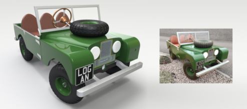
The simplicity of the body shape made this the ideal choice for a pedal car home DIY project. This has been a low budget one-off manufacture and therefore many of the parts are recycled from surplus joinery materials. SOLIDWORKS 3D CAD tools have been utilised to take what may have been bonfire wood and turned it into something exciting.

Basic design specification:
- Ergonomically suited for a 2-3 year old child
- Traditional forward push pedal arms that link to a rear axle crank (to prevent feet being trapped)
- 4:1 steering ratio to give light steering and sufficient movement at the hand wheel
- Closely represents a scaled model of the Series 1
Appropriately sized, cheap, readily
available wheels (regularly seen on heavy goods trolleys) were sourced and
provided a starting reference. With the
wheel diameter in mind, a sketch picture showing elevations is scaled and traced
to give a profile ready for building features.

The chassis and body are both created as a
single part file containing multiple solid bodies. This gives the advantage of modelling the
overall shape in one environment.
A
common misconception is that SOLIDWORKS Weldment functions apply specifically to
steel structural members.
However in this case we can regard the multibody wooden framework as a
weldment structure from which we can produce a cut list. By applying bounding
boxes, the resulting cut list properties contain length, width and thickness
for each individual part of the structure.

When it comes to designing the steering
linkage and drivetrain components it is incredibly useful to have full control
within the assembly environment. Update
the dimension of a referenced part and you can see the resulting behavior immediately,
without the need to move away from your preferred view orientation. All instances of the modified part rebuild
simultaneously.

Pictorial drawing views with coinciding Bills
of Material are effortless to create either in a top or sub assembly
level. This is a convenient way of
communicating details, parts lists and assembly instructions for individual
areas of the design.

Nice to see another Series 1 roll off the
production line!


By Kyle Craig
Applications Engineer